
How to Choose the Right Boring Machine for Industrial Applications
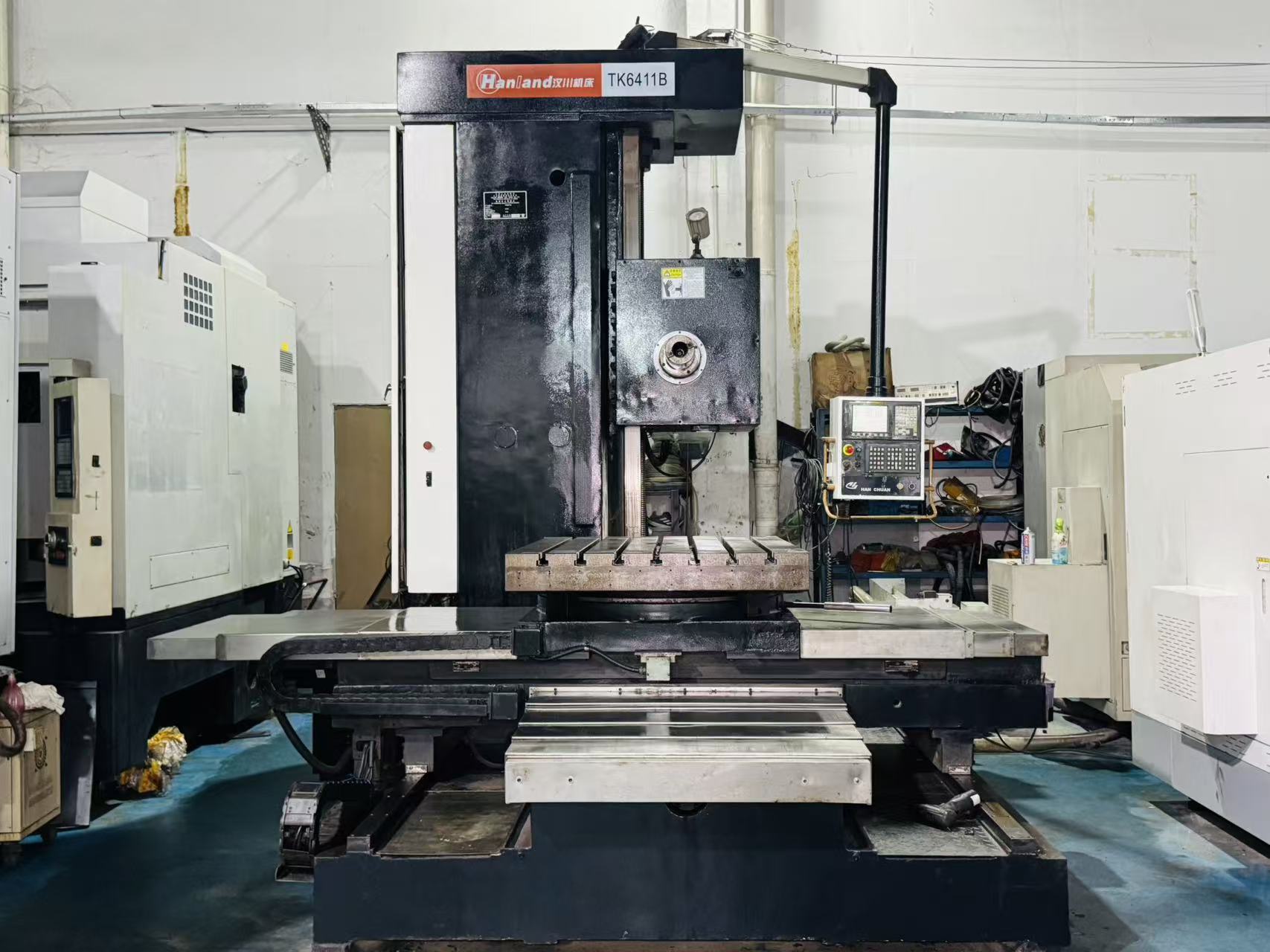
Choosing a boring machine usually begins with a practical problem: a worn pivot bore on an excavator, an out-of-round bearing housing, a large fabricated component that needs accurate machining, or a production part that requires repeatable internal diameters. The right choice depends less on the machine label and more on where the work happens, how the bore must be restored, and how consistently the required result must be achieved.
A boring machine that is well suited to in-shop work may be impractical at a mine, shipyard, construction site, or equipment yard. Conversely, a portable unit can be the efficient answer for in-place repair but may not be the preferred option for high-volume machining. A sound boring machine selection process starts with the component and working conditions, then compares machine configurations against those requirements.
Recognize When a Boring Machine Is the Right Solution
Industrial boring is typically required when an existing hole needs to be enlarged, aligned, resurfaced, or restored to a controlled diameter. Common situations include worn pin bores in construction equipment, damaged bearing seats, misaligned mounting holes, gearbox housings, structural fabrications, and large machine frames.
Before purchasing an industrial boring machine, determine whether the job involves:
- Restoring a worn or damaged bore to accept a pin, bushing, bearing, or sleeve.
- Correcting the alignment of two or more coaxial holes.
- Machining an internal diameter after welding, sleeving, or fabrication.
- Creating accurate bores in large workpieces that cannot be moved easily.
- Producing repeatable bore geometry in a controlled manufacturing environment.
If the part can be transported and production repeatability is the priority, a fixed machine may be appropriate. If moving the component would cause excessive downtime, transport cost, or disassembly work, on-site boring equipment deserves close consideration.
Start With the Actual Bore and Work Envelope
The bore itself establishes the first set of selection limits. Measure the current diameter, target diameter, bore length, wall condition, and the distance between related holes. Also consider whether facing, counterboring, weld buildup machining, or bushing-seat preparation will be required during the same setup.
Do not evaluate diameter in isolation. A machine must also accommodate the boring bar length, tool travel, available mounting area, and access around the component. For example, a repair may appear straightforward based on bore size but become difficult when the machine must operate inside a confined equipment frame or between closely spaced structural members.
Ask suppliers to confirm the usable working range for the configuration being quoted, including the tooling and mounting arrangement needed for the intended job. This is more useful than comparing a headline capacity without considering the complete setup.
Boring Machine Selection Table
| Machine Type | Best-Fit Applications | Main Advantage | Points to Evaluate |
|---|---|---|---|
| Portable boring machine | Field repair, heavy equipment, large fixed assets, limited-access locations | Machining can be completed at the workpiece location | Mounting method, site power, access, transport weight, operator setup requirements |
| Portable line boring machine | Aligned pin bores, bearing housings, articulated equipment, structural bores | Restores alignment across one or multiple bores | Boring bar support, alignment method, bore spacing, weld-repair workflow |
| Horizontal boring machine | Large shop-based workpieces, housings, frames, heavy fabrication | Rigid machining platform for substantial components | Table capacity, work envelope, handling equipment, floor space, setup time |
| CNC boring machine | Repeat production, complex geometry, controlled machining programs | Programmable repeatability and process consistency | Part volume, programming needs, fixturing, inspection process, operator capability |
Match the Machine Type to the Job Location
Portable Boring Machines for On-Site Repair
A portable boring machine is often selected when the component is too large, too costly, or too disruptive to remove. This is common in earthmoving equipment, cranes, agricultural machinery, ship repair, industrial plants, and heavy fabrication.
The key advantage is reduced component movement. However, field performance depends on secure mounting, correct alignment, stable power supply, sufficient access, and the ability to protect the machining area from site conditions. Procurement teams should assess the complete field workflow, including transport cases, setup tools, cutting tools, measuring equipment, and operator training.
Line Boring Machines for Coaxial Bore Repair
A line boring machine is designed for work where the relationship between bores matters as much as the diameter of each individual hole. Typical examples include boom and stick pivots, loader frames, hinge points, and multi-bore bearing supports.
For these repairs, the machine must establish a reliable centerline through the bore set. The chosen system should suit the number of bores, their spacing, the available support locations, and the repair sequence. When weld buildup is part of the job, consider how the equipment will be repositioned for machining after welding and cooling.
Horizontal and CNC Machines for Controlled Shop Work
Horizontal boring machines are generally suited to large, transportable workpieces requiring stable shop machining. They can be a practical choice for fabricated structures, large housings, and components that benefit from a rigid fixture and controlled working environment.
CNC boring machines become more relevant when parts are repeated, multiple features must be machined in defined locations, or the process requires program-based consistency. Their value is strongest when production volume, part complexity, and quality-control requirements justify the investment in programming and fixturing.
Balance Accuracy, Rigidity, Power, and Portability
Accuracy requirements should be stated in the job specification before equipment is selected. Consider final diameter, roundness, straightness, bore-to-bore alignment, surface condition, and the fit required for the mating pin, bushing, or bearing. The machine is only one part of achieving the result; fixturing, alignment practice, cutting tools, measurement, and operator method are equally important.
Rigidity affects cutting stability and finish, particularly on larger diameters, longer bores, or welded repair areas. Power should be evaluated against the material, cutting depth, tooling, and expected duty cycle. At the same time, more power or a heavier machine is not automatically better for field repair. A portable system must remain practical to transport, mount, and operate safely at the job site.
The most effective industrial boring machine is therefore the one that provides adequate rigidity and capability without creating unnecessary handling or setup burdens.
Questions to Put to a Manufacturer or Supplier
Supplier support can materially affect the value of a boring machine purchase, especially where the application is unusual or the equipment will be used across several types of repairs. Rather than relying only on a standard product description, provide drawings, photographs, bore dimensions, material information, and job-site constraints for application review.
Useful procurement questions include:
- Which configuration is appropriate for the planned bore sizes, lengths, and access conditions?
- What mounting, alignment, facing, or weld-repair accessories are needed for the full job?
- Which consumables and replacement parts should be planned for routine operation?
- Can the supplier provide application guidance, operating documentation, training options, or technical support?
- For OEM requirements, can the supplier discuss configuration, branding, packaging, documentation, and supply-chain expectations?
For buyers managing fleets, repair centers, or equipment distribution, it is also important to assess parts availability and the supplier's ability to support a consistent equipment package over time. These points should be verified during sourcing rather than assumed from a product listing.
FAQ: Selecting an Industrial Boring Machine
Should I choose a portable boring machine or move the part to a workshop?
Choose portable equipment when removing the component creates excessive downtime, cost, or disassembly effort. Workshop machining may be preferable when the part is readily transportable and the job benefits from fixed-machine capacity, controlled fixturing, or repeated production.
When is line boring necessary?
Line boring is necessary when two or more bores must share a common axis, such as pivot points, hinge bores, or aligned bearing locations. It is particularly valuable when wear has caused misalignment as well as diameter loss.
Is the largest bore capacity the most important buying criterion?
No. Bore range matters, but mounting access, boring length, alignment requirements, power source, tooling, portability, and the types of components being repaired are often equally important. Select for the jobs performed most often, while allowing reasonable capacity for planned work.
What information should be prepared before requesting a quotation?
Provide the existing and finished bore dimensions, bore length, material, number and spacing of related bores, required finish or fit, photographs or drawings, available workspace, power conditions, and whether welding or facing is required. This information helps a supplier recommend a workable configuration rather than a generic machine.
Make Selection Around the Full Repair or Production Process
A successful boring machine selection connects the equipment to the complete machining task: inspection, mounting, alignment, cutting, measurement, and final fit. Begin with the actual component and job location, then compare portable, line boring, horizontal, and CNC options according to the work envelope and production need.
By defining bore requirements, access constraints, accuracy expectations, power availability, and future application range before purchase, industrial buyers can select equipment that supports productive repair or machining work without paying for capability that does not fit their operation.
More Articles
-
Used TOSHIBA BTD-13F.R22 Boring and milling machineThis used Toshiba BTD-13F.R22 CNC floor-type boring and milling machine is a Japanese-built heavy machining solution equipped with TOSNUC 888 control, 3000 × 2300 × 1600 × 700 mm X/Y/Z/W travel, a Ø130 mm boring spindle, a BT50 geared spindle, 2500 rpm spindle speed, and a 2200 × 1800 mm table. It is suitable for manufacturers machining large housings, dies, molds, aerospace structures, automotive tooling, medical equipment frames, and precision electronic equipment components. Stock number 812216 is in stock, available now, and available for inspection, making it a cost-effective option for shops that need to add large-part CNC boring and milling capacity without waiting for a new machine lead time. Core Specifications and What They Mean in Production The Toshiba BTD-13F.R22 is designed for large workpieces that require both working range and rigidity. For a production manager, the key question is not only whether the machine can cut the material, but whether its travels, spindle size, table area, tooling interface, and control system match the parts scheduled for regular production. This machine combines long-axis capacity with a Ø130 mm boring spindle, making it suitable for medium-to-large machining work where hole accuracy, face milling access, and multi-side machining are important. CNC System: TOSNUC 888A Toshiba CNC platform for multi-axis boring and milling operations, suitable for programmed machining cycles and repeatable large-part production. X/Y/Z/W Travel: 3000 × 2300 × 1600 × 700 mmThe machine offers a long working envelope for large frames, base plates, molds, tooling blocks, and structural components. Spindle Taper: BT50 Geared HeadBT50 tooling supports heavy milling cutters, boring bars, face mills, drills, and roughing tools commonly used in industrial machining. Spindle Speed: 2500 rpmThe speed range supports boring, drilling, and general milling in steel, cast iron, aluminum, and other common engineering materials. Boring Spindle Diameter: Ø130 mmThe large boring spindle provides the rigidity needed for deep boring, facing, and large-diameter hole machining. Table Size: 2200 × 1800 mmThe table area provides practical support for large workpieces, fixtures, mold bases, housings, and tooling plates. Table Indexing Accuracy: 1/10000Fine table indexing supports angular positioning when machining multiple faces or features around a workpiece. Tool Magazine Capacity: 38 ToolsThe tool magazine allows multiple operations to be prepared in one setup, reducing manual tool changes during complex jobs. Tooling Match and Part Fit Tooling compatibility is one of the main reasons buyers consider a used Toshiba BTD-13F.R22 CNC floor-type boring and milling machine. The BT50 geared spindle is a heavy industrial interface widely used on boring mills, machining centers, and large milling machines. For a shop already using BT50 holders, this can simplify toolroom integration. For a plant planning new tooling, BT50 provides a practical platform for boring heads, shell mills, indexable drills, face mills, and long-reach tools. Where the Ø130 mm Boring Spindle Matters A Ø130 mm boring spindle is valuable for work involving large bores, bearing seats, hydraulic cylinder housings, gearbox housings, turbine-related parts, and precision mounting holes. Compared with lighter milling machines, this spindle diameter gives the machine a stronger foundation for boring operations where tool overhang and cutting pressure can affect surface finish and geometry. Table Size and Fixturing Space The 2200 × 1800 mm table provides space for substantial fixtures and large workpieces. This matters in mold making, automotive die work, aerospace tooling, and machinery base machining because the fixture itself often takes up a significant portion of the table. Buyers should compare the table dimensions with the maximum length, width, clamping allowance, and fixture height of their typical workpieces. One Machine, Many Applications Automotive: die components, gearbox housings, engine-related fixtures, tooling plates, and large production equipment parts. Aerospace: structural components, tooling frames, fixture bases, and large aluminum or alloy workpieces requiring multi-face access. Mold making: mold bases, cavity support blocks, large plates, and deep pocket machining where reach and rigidity matter. Medical devices: machine frames, precision housings, equipment bases, and fixture tooling for regulated production environments. Electronics: large equipment frames, semiconductor-related tooling, machine bases, and precision aluminum structures. Frequently Asked Questions What does the 3000 × 2300 × 1600 × 700 mm travel mean for part selection? It defines the working reach of the X, Y, Z, and W axes. This travel range is suitable for large parts, tall fixtures, deep bores, and multi-face machining where a smaller machining center may require repeated repositioning. Is the BT50 geared spindle suitable for heavy milling and boring? Yes. BT50 is a heavy industrial tooling interface, and the geared head is appropriate for large cutters, boring heads, drills, and face mills used on steel, cast iron, mold bases, and equipment components. What part types are a good match for the Ø130 mm boring spindle? The Ø130 mm spindle is suitable for gearbox housings, bearing bores, hydraulic equipment bodies, mold bases, machine frames, and structural components that require rigid boring and stable cutting. How should buyers interpret the 2500 rpm spindle speed? The 2500 rpm speed is practical for general boring, drilling, and milling. Buyers should compare tool diameter, material, and surface finish requirements to confirm whether the speed range matches their process plan. Does the 2200 × 1800 mm table fit large molds and tooling plates? It can fit many large molds, plates, housings, and fixtures, but buyers should check part size together with clamping allowance, fixture thickness, tool reach, and required machining clearance. Why is the 38-tool magazine important for production planning? A 38-tool magazine allows multiple tools to be prepared for roughing, finishing, drilling, boring, and chamfering. This helps complex workpieces move through more operations in one setup. Who should inquire about this used Toshiba BTD-13F.R22? It is suitable for factories needing an in-stock CNC floor-type boring and milling machine for large-part machining, especially in automotive, aerospace, mold making, medical device equipment, and electronics equipment production.

-
Used AWEA SP3016 CNC Gantry Milling Machine for Production EvaluationThis used AWEA SP3016 CNC Gantry Milling Machine is a large-table, double-column CNC gantry mill with a Fanuc 18i-MB CNC system, 3060 mm X-axis travel, 1600 mm Y-axis travel, 760 mm Z-axis travel, a 3000 x 1500 mm table, and 10,000 kg table load capacity. It is suitable for mold bases, fixture plates, large structural parts, and precision-machined plates used in automotive, aerospace, mold making, medical device tooling, and electronics tooling plants. Stock number 812113 is in stock, available for inspection, and positioned as an immediate capacity upgrade for factories that need a cost-effective used gantry milling machine without waiting for a new build. Core Specifications and What They Mean in Production The AWEA SP3016 is a CNC gantry milling machine built for workpieces that are too large, too heavy, or too wide for a conventional vertical machining center. Its double-column design, long X-axis travel, and wide worktable make it practical for machining long plates, die shoes, mold bases, structural components, and parts with multiple features in a single setup. For procurement and process engineering teams, the key question is not only whether the machine can cut the part, but whether the travel, table size, spindle clearance, and load capacity match the actual production envelope. The 3060 mm X-axis travel supports long workpieces and allows machining across nearly the full length of the 3000 mm table. This is important for mold plates, automotive fixture bases, aerospace panels, and long machine frames where moving the part between operations would add setup time and increase alignment risk. The 1600 mm Y-axis travel is useful for wide plates and tooling blocks, while the 760 mm Z-axis travel provides room for taller workpieces, fixtures, and tool length. The 1700 mm distance between the double columns defines the practical maximum width for the part and fixture passing through the gantry opening. In production planning, this should be checked against the largest raw workpiece size, not only the finished part size. The 200 to 960 mm spindle nose-to-table distance defines the available vertical clearance range. This affects whether the machine can accommodate thick molds, tall fixtures, long cutting tools, or stacked workholding. The 3000 x 1500 mm table and 10,000 kg maximum table load make this Yawei gantry mill suitable for heavy machining setups. Heavy mold bases, die plates, castings, and steel fixtures can be clamped with enough table area for locating blocks and clamps. The 22 / 26 kW main motor power supports milling work where cutter diameter, material hardness, and depth of cut require more power than a smaller machining center can typically provide. Tooling Match and Part Fit A CNC gantry milling machine is often selected when the workpiece footprint is the limiting factor. The AWEA SP3016 should be evaluated against the actual dimensions of your tooling, raw stock, clamps, and required cutter reach. With a 3000 x 1500 mm worktable and 3060 x 1600 mm travel range, it is well suited for large plates, mold bases, press tooling components, and large fixture bodies. The table size can also support several smaller components in one setup when batch flexibility is more important than dedicating the spindle to one small part at a time. Suitable Workpiece and Tooling Examples Automotive: die plates, fixture bases, checking fixture frames, battery tray tooling plates, and large structural machining. Aerospace: aluminum structural plates, fixture tooling, long ribs, and large-format machining setups where X-axis travel is critical. Mold making: plastic mold bases, die shoes, core and cavity support plates, and large insert machining where table load and spindle clearance matter. Medical devices: mold tooling, precision fixture plates, and production tooling for large or multi-cavity components. Electronics: large die sets, fixture plates, heat sink tooling, and precision base plates used in assembly or forming processes. The Fanuc 18i-MB CNC system is a widely used industrial control platform for milling applications. For plants already running Fanuc-based machines, operator workflow, program format, and shop-floor familiarity may be easier to align than with a completely different control environment. The control should still be checked during inspection for program input, axis movement, alarm history, and interface condition. Frequently Asked Questions What does the 3060 mm X-axis travel mean for part selection? The 3060 mm X-axis travel allows the cutter to cover long workpieces close to the full length of the 3000 mm table. It is useful for mold bases, fixture plates, aerospace plates, and long structural components where machining in one setup is preferred over repositioning. Can the Yawei SP3016 handle heavy mold and die components? The machine has a 3000 x 1500 mm table and a maximum table load of 10,000 kg. That makes it suitable for heavy mold bases, die shoes, steel plates, and large fixture bodies, provided the workpiece footprint and clamping method fit the table and gantry opening. How should I judge whether my tooling fits between the columns? Check the 1700 mm distance between the double columns against the widest raw workpiece, not only the finished part. Include side clamps, fixture plates, lifting clearance, and any protruding features when deciding whether the setup can pass safely through the gantry. Why is the 200 to 960 mm spindle nose-to-table distance important? This range defines the vertical working envelope. A tall fixture, thick mold base, long holder, or extended cutter can reduce available clearance. Before purchase, add together the table setup height, workpiece height, tool holder length, cutter length, and required machining depth. Is this used CNC gantry milling machine suitable for mixed production? Yes, if your mixed production includes large plates, tooling bases, molds, fixtures, and structural parts. The SP3016 is best viewed as a versatile all-round machine for factories that need one large-capacity machine to support multiple industries and part families. Is the Yawei SP3016 CNC Gantry Milling Machine in stock? Yes. Stock number 812113 is in stock and available now for inspection and shipment. Send an inquiry with your part size, material, and tooling requirements to evaluate production suitability.

-
Used Okuma MCR-A5CII CNC Gantry Milling Machine SpecificationsThis used Okuma MCR-A5CII CNC gantry milling machine is a Japan-built double-column machining solution with 4200 x 3100 x 800 mm X/Y/Z travel, 1000 mm W-axis travel, a 2000 x 4000 mm table, 10000 rpm spindle speed, a 60-tool magazine, and multiple milling heads for five-face machining. It is suitable for manufacturers machining large plates, mold bases, structural components, aerospace fixtures, automotive tooling, medical equipment plates, and electronics production tooling. Stock No. 812100 is in stock, available now, and ready for immediate shipment, making it a practical option for plants that need large-format machining capacity without waiting for new-machine lead time. Core Specifications and What They Mean in Production The Okuma MCR-A5CII is a CNC gantry milling machine and is also commonly evaluated as a double-column machining center for large workpieces. Its value is not only in the travel figures, but in how those figures affect part envelope, tool access, setup strategy, and production flow. For procurement managers and process engineers, the key question is whether the machine can hold the target workpiece, reach the required faces, and support the necessary tooling without excessive re-clamping. Machine category CNC gantry milling machine / double-column machining center Brand and model Okuma MCR-A5CII Origin Japan Year 2014 X/Y/Z axis travel 4200 x 3100 x 800 mm W-axis travel 1000 mm Table size 2000 x 4000 mm Distance from table surface to spindle nose 1650 mm Maximum spindle speed 10000 rpm Gantry width 2650 mm Floor space 6680 x 10730 mm Machine net weight 37000 kg Tool magazine capacity 60 tools Included configuration Four-axis linear scales, T301 vertical milling head, T302 90-degree vertical milling head, T303BC five-face milling head The 4200 mm X-axis travel and 4000 mm table length support long plates, mold bases, machine frames, and fixture plates that are difficult to process efficiently on smaller vertical machining centers. The 3100 mm Y-axis travel and 2650 mm gantry width are important when reviewing wide workpieces, because the part must fit through the column opening while still allowing clearance for clamps, edge machining, and tool approach. The 800 mm Z-axis travel, 1000 mm W-axis travel, and 1650 mm distance from the table surface to the spindle nose help determine whether tall parts, riser setups, angle plates, and deep cavities can be machined. In real production, this matters for large molds, aerospace fixture blocks, welded structures, and medical or electronics tooling plates where multiple face depths may be required in a single setup. The 10000 rpm maximum spindle speed gives the machine a broader process window than a low-speed gantry mill used mainly for heavy roughing. It can be considered for mold finishing, aluminum aerospace components, fixture plates, and general large-part milling where both material removal and surface finish are required. Final suitability still depends on cutting tools, material, clamping method, programmed feeds, and the condition verified during inspection. How the Key Specs Affect Machine Selection Travel and Table Size The first selection filter is part size. A 2000 x 4000 mm table does not mean every 2000 x 4000 mm part will be easy to machine; buyers should allow space for clamps, stops, side access, tool overhang, and chip evacuation. The 4200 mm X-axis travel gives useful longitudinal reach across the table length, while the 3100 mm Y-axis travel helps cover wide parts and side positioning. For production managers, this can reduce the need to split large components into multiple setups or outsource oversized machining. Height, Reach, and W-Axis Stroke The 1650 mm table-to-spindle-nose distance is important for tall components, tombstone-style fixtures, and riser block setups. Combined with 800 mm Z-axis travel and 1000 mm W-axis travel, it gives the machine reach for deep features and higher workpiece envelopes. This matters in mold making and structural machining, where the part may include ribs, steps, pockets, or cast and welded geometry above the table surface. Spindle Speed and Tool Magazine A 10000 rpm spindle is helpful when the production mix includes aluminum, cast iron finishing, mold surfaces, and smaller tools used on a large workpiece. The 60-tool magazine supports complex programs with roughing, semi-finishing, finishing, drilling, tapping preparation, chamfering, and side-face tools in the same cycle. For factories running low-volume, high-mix work, that tool capacity can reduce setup interruptions and keep the machine productive during long programs. Machine Mass and Floor Requirement The 37000 kg net weight and 6680 x 10730 mm floor space should be reviewed early in the buying process. This machine is intended for a plant with proper space planning, foundation readiness, rigging access, and loading access. A factory currently relying on smaller machining centers should confirm not only part fit, but also the installation footprint and production flow around the machine. Frequently Asked Questions What do the 4200 x 3100 x 800 mm travels mean for part size? These travels define how far the machine axes can move in X, Y, and Z. In production, they help determine whether the cutter can reach the full work area after the part, clamps, and fixtures are installed. For this MCR-A5CII, the 4200 mm X travel and 3100 mm Y travel support large plates, mold bases, fixtures, and structural components, while the 800 mm Z travel helps with depth and height variation. Is the 2000 x 4000 mm table suitable for large mold bases? Yes, the 2000 x 4000 mm table class is well suited for many large mold bases, die bases, and tooling plates. Buyers should still compare the actual workpiece size with clamp space, tool approach, side-machining requirements, and the 2650 mm gantry width before confirming fit. Why is the 1000 mm W-axis travel important? The W-axis provides additional vertical movement for the crossrail or spindle system, depending on machine configuration. For buyers, it matters when machining tall parts, deep pockets, large fixtures, or workpieces with multiple height levels. Together with the 1650 mm table-to-spindle-nose distance, it improves the machine’s ability to handle taller setups. How does the 10000 rpm spindle affect material suitability? A 10000 rpm maximum spindle speed gives more flexibility for finishing and smaller-diameter tooling than a low-speed-only gantry mill. It can be useful for mold finishing, aluminum components, fixture plates, and precision hole patterns. Material suitability still depends on tool type, cutting parameters, workholding, and verified spindle condition. What is the benefit of the T301, T302, and T303BC head package? The T301 vertical milling head supports standard top-face machining. The T302 90-degree head supports side-face and horizontal-feature machining. The T303BC five-face milling head expands access to multiple sides of the workpiece, which can reduce re-clamping for molds, die bases, structural parts, and large fixtures. Who should consider this used Okuma MCR-A5CII CNC gantry milling machine? It is best suited to factories and job shops that need large-part machining capacity for automotive tooling, aerospace fixtures, mold making, medical equipment plates, electronics tooling, and general machinery components. It is especially attractive when current equipment lacks table size, axis travel, or multi-face machining access.

-
Used FEMCO BMC-110R1 CNC Boring and Milling MachineStock Number: 811824 | Available for Immediate Inspection The FEMCO BMC-110R1 is a heavy-duty floor-type CNC boring mill engineered for complex, large-scale part processing. Featuring a 4000kg table load capacity, 3-axis box way construction, and a 60-tool automatic tool changer (ATC), this machine is built for shops handling large components, precision molds, and multi-sided machining. This 2012 model is production-ready and available for immediate inspection. Core Specifications and Shop Floor Performance Beyond the raw data, the BMC-110R1 is designed to deliver stability and efficiency for demanding production environments. Specification Details Model FEMCO BMC-110R1 CNC System Fanuc 21i-MB Table Load Capacity 4000 kg X-Axis Travel 1400 mm Y-Axis Travel 1390 mm Z-Axis Travel 1050 mm W-Axis Travel 500 mm Tool Changer 60-Tool ATC Rotary Table Accuracy 0.001° Guideways 3-Axis Box Ways Additional 4th Axis with Linear Scale Rigidity and Vibration Damping The 3-axis box way construction provides the foundation for this machine's performance. Unlike linear guide systems, which prioritize rapid traverse speeds, box ways offer a larger contact surface area. This is critical for heavy-duty milling and boring, where superior vibration damping is required to achieve tight tolerances and high-quality surface finishes on dense workpieces. The Significance of the W-Axis The 500mm W-axis (quill travel) allows the spindle to extend significantly from the machine head. In practical production, this is vital for deep-hole boring or reaching into deep cavities of complex housings. This capability eliminates the need to reposition heavy workpieces, thereby maintaining positional accuracy and reducing setup time. Capacity for Complex Tooling The 60-tool ATC is a significant advantage for a machine in this class. It supports a wide range of cutters, drills, and boring bars, enabling complex, multi-step machining sequences without manual intervention. This is particularly beneficial for "lights-out" production or high-mix, low-volume shops where frequent tool changes are standard. Applications and Workpiece Compatibility The BMC-110R1 offers exceptional versatility. Its combination of a 4000kg table capacity and 0.001° indexing accuracy bridges the gap between a traditional heavy-duty boring mill and a high-precision machining center. Ideal Applications: Large Industrial Castings: Engine blocks, pump housings, and gearbox casings requiring heavy material removal. Precision Molds and Dies: The 0.001° rotary table enables the precise angular machining required for complex mold parting lines and cooling channels. Aerospace Components: Structural frames and large housings demanding high positional accuracy across multiple faces. Energy Sector Parts: Flanges, valve bodies, and turbine components requiring both structural integrity and geometric precision. The 4th axis with a linear scale ensures that table indexing is verified by the scale rather than relying solely on the motor encoder. This provides the reliability needed for high-tolerance work where angular deviation could lead to scrapped parts. Why the BMC-110R1 Fits Your Production Needs When selecting a used boring mill, the BMC-110R1 offers distinct advantages for production managers: Fanuc 21i-MB Control: Widely recognized for reliability and ease of integration. Operators familiar with Fanuc will face a minimal learning curve, reducing downtime during commissioning. Optimized Work Envelope (X:1400, Y:1390, Z:1050): This machine is perfectly sized for medium-to-large parts. It provides an ideal balance of footprint and capacity for components that exceed standard VMC envelopes but do not require massive floor-type boring mills. Operational Versatility: By combining boring capabilities (W-axis) with milling capabilities (ATC and rotary table), this machine acts as a "one-stop" station, reducing the need to move heavy parts between machines—a process that often introduces error and increases handling time. Is This Machine Right for Your Facility? The FEMCO BMC-110R1 is an ideal solution if: You are currently outsourcing large, complex parts due to capacity constraints. Your current VMCs struggle with vibration during heavy boring or face milling on cast iron or steel. You require multi-sided machining that demands precise angular indexing. You need a machine capable of both aggressive roughing (thanks to box ways) and high-precision finishing (thanks to the 0.001° indexing and Fanuc control). While this machine may be over-specified for small, light parts, it is a robust solution for shops dealing with heavy, complex, or high-value components looking to increase throughput. Frequently Asked Questions Q: Is the 4th axis on this BMC-110R1 suitable for continuous milling or just positioning? A: The 0.001° rotary table is designed for high-precision positioning. While robust, its primary advantage is the ability to index to precise angles for multi-sided machining, making it well-suited for applications requiring high angular accuracy. Q: What is the main advantage of the box ways on this machine compared to linear guides? A: Box ways provide superior vibration damping and rigidity. This is critical for heavy-duty boring and milling operations where you need to maintain surface finish and dimensional accuracy while taking deep cuts in tough materials. Q: Can the 60-tool ATC handle heavy boring bars? A: Yes, the ATC is designed to manage a variety of tooling, including standard boring bars. Always ensure your tooling setup adheres to the weight and length limits specified in the original manufacturer’s manual for the tool changer mechanism. Q: Is this machine suitable for mold making? A: Yes. The combination of the rigid box-way structure (for mold base machining) and the 0.001° rotary table (for precision angular machining of mold cavities) makes it a versatile choice for mold shops handling medium-to-large molds. Q: What does the W-axis travel specifically do for my production? A: The W-axis allows the spindle to extend outward. This is essential for boring deep holes or reaching into complex part geometries without moving the workpiece, which saves time and maintains alignment accuracy.